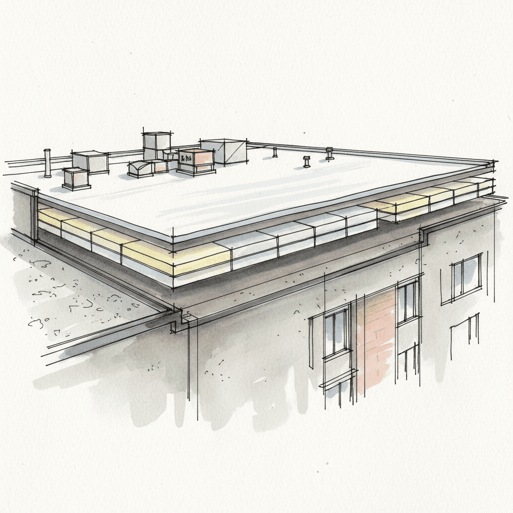
The structural load of solar panels is the total static and dynamic force that a solar energy system exerts on a roof, the top covering of a building designed to provide protection against rain, snow, sunlight, and wind. The failure to correctly analyze this load before installation introduces unacceptable risk to the structural integrity and weatherproofing capability of your home. A solar installation is a structural engineering project first and an electrical project second. The industry standard often inverts this priority, leading to predictable failures in the roofing system.
This analysis is not for homeowners seeking the lowest possible price. It is a systematic methodology for meticulous individuals who require a predictable, chaos-free outcome. If your primary decision-making metric is the lowest bid, we are not the right company for you. Our process is designed to eliminate surprises, protect your home as the primary asset, and ensure the 25-year lifespan of your solar array is not compromised by a premature roof failure. The enemy is the disorganized, corner-cutting approach that dominates the residential solar industry. Our weapon is a non-negotiable, process-driven protocol.
Structural Load Analysis: Verifying Your Roof’s Support Capacity
Before a single solar panel is considered, your roof’s ability to support the additional weight must be verified. A roof’s function as a support structure is fundamental. The introduction of a solar array, which can weigh several thousand pounds, fundamentally alters the forces acting upon that structure. This requires a formal analysis, not an assumption.
Calculating Dead Loads vs. Live Loads for Solar Arrays
Load calculation is a foundational engineering principle. The forces on your roof are categorized into two types:
- Dead Load: This is the static, permanent weight of the solar installation itself. It consists of the solar panels, the metal racking system, and all mounting hardware. A typical solar panel weighs around 40 pounds, and a complete system adds 3-5 pounds per square foot (psf) to the existing roof structure. This is a constant, distributed load.
- Live Load: This refers to the temporary, variable forces acting on the roof. The primary live loads to consider are snow accumulation (snow load) and wind pressure (wind load). In regions with heavy snowfall, the additional weight of snow on top of the panels can be significant. Wind creates both downward pressure and, more critically, upward lift forces that can pull panels and roofing materials off the structure.
These loads must be calculated and compared against local building codes and the original design capacity of your roof framing.
Rafter and Truss Inspection: Identifying Points of Failure
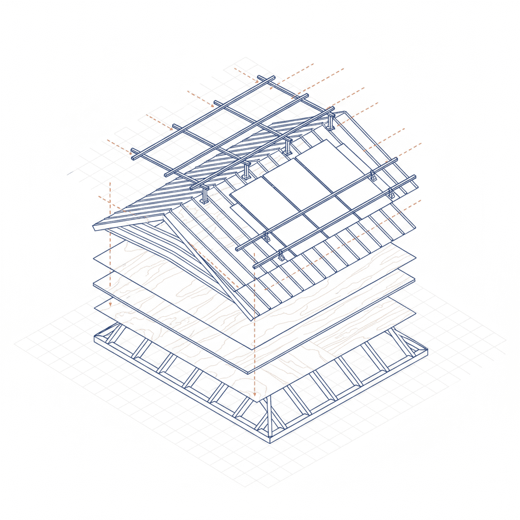
The roof framing system, composed of either rafters or pre-engineered trusses, is the skeleton that transfers all roof loads to the building’s load-bearing walls. This system is the single most critical element in supporting a solar array. A visual inspection is mandatory to identify potential points of failure.
The inspection must verify:
- Structural Integrity: There must be no visible sagging, cracking, splitting, or twisting in any rafter or truss member.
- Proper Connections: All connections between framing members, and between the framing and the walls, must be secure.
- Modifications: Any past modifications, such as cutting a rafter to install a skylight, must be evaluated to ensure they were properly reinforced.
Any sign of weakness in the roof framing is an immediate stop. Proceeding without structural reinforcement is negligent.
The Role of Sheathing in Uniform Load Distribution
Roof sheathing, typically plywood or Oriented Strand Board (OSB), is the layer of material fastened to the top of the rafters. Its function is to create a solid surface for roofing materials and to distribute point loads across multiple framing members. Solar panel mounts create concentrated point loads. The sheathing’s thickness and condition are critical for preventing these mounts from pulling out under wind uplift or causing localized damage. The inspection must confirm the sheathing is of adequate thickness (e.g., minimum 1/2 inch) and that there is no rot, delamination, or water damage, particularly around existing roof penetrations.
Material Lifespan Assessment: Synchronizing Roof and Panel Longevity
Installing a solar array with a 25-year production warranty onto a roofing system with only 10 years of remaining service life is a significant financial mistake. The cost to remove the entire solar array, replace the roof, and then reinstall the array can negate years of energy savings. The lifespan of the top covering must match or exceed the lifespan of the solar panels.
Asphalt Shingle Viability: Granule Loss and Sealant Integrity Analysis
Asphalt shingles are the most common roofing material, but their condition must be rigorously assessed. Key indicators of remaining lifespan include:
- Granule Loss: The stone granules protect the underlying asphalt from UV degradation. Significant granule loss, visible in gutters or as bald patches on the shingles, indicates the end of the roof’s service life.
- Sealant Strip Integrity: A thermally activated asphalt sealant strip on each shingle bonds it to the course below, providing wind resistance. If this sealant has failed, the shingles are brittle and susceptible to wind uplift. A roof in this condition cannot support the amplified wind loads from a solar array.
- Flexibility: Older shingles become brittle. If lifting a shingle tab causes it to crack or break, the roof is too old for a solar installation.
Metal Roofing: The Ideal Platform for Non-Penetrating Solar Integration
A standing seam metal roof is the optimal platform for solar panels. Its longevity, typically 50 years or more, aligns perfectly with the solar equipment’s lifespan. More importantly, it allows for a non-penetrating installation. Specialized clamps attach directly to the raised seams of the metal panels, securing the solar racking system without creating a single hole in the roof deck. This method completely eliminates the primary risk of roof leaks associated with solar installations and is the superior methodology for ensuring long-term weatherproofing.
Tile and Slate Systems: Specialized Mounting and Durability Protocols
Clay tile, concrete tile, and slate roofs offer exceptional durability but present unique challenges for solar installation. These materials are brittle and can easily crack or break under the weight of installers or from the point loads of mounting hardware. The installation requires specialized mounting hooks that slide under the tiles and attach directly to the roof rafters. The racking system is then elevated above the surface of the tiles. This preserves the tile’s natural water-shedding channels and avoids direct contact that could lead to breakage. This is a specialized task that standard solar installers are not equipped to handle correctly.
Weatherproofing Protocol: Ensuring Absolute Protection Post-Installation
A solar installation introduces dozens, if not hundreds, of new penetrations to your roof’s water-shedding surface. Every penetration is a potential leak. The protocol for weatherproofing these points is not a detail; it is the most critical aspect of the installation process. The primary function of a roof is to provide protection against water penetration.
Penetration Flashing Systems: The Most Critical Failure Point
Relying on sealant or caulk to waterproof a roof penetration is a guaranteed future failure. Sealants break down under UV exposure and thermal cycling. The only acceptable method is a mechanical flashing system. For each mounting point, a metal flashing is integrated into the roofing layers. It is installed in a lapped manner, with the upper shingle course covering the top of the flashing, creating a path where water is diverted over and around the penetration. This system does not rely on a chemical sealant for its primary waterproofing function. This is a non-negotiable standard.
Evaluating Existing Underlayment and Water Shields
The underlayment is the secondary water barrier located between the sheathing and the final roofing material. Before any work begins, the condition of this layer must be considered. On an older roof, the underlayment may be brittle or compromised. In colder climates, a self-adhering ice and water shield is a critical component of the building envelope, providing protection against ice dams. A solar installation must not compromise this secondary defense system. If the underlayment is in poor condition, the only correct course of action is to replace the roof before installing solar.
Maintaining Wind Resistance Ratings with Racking Systems
Roofing systems are rated for wind resistance, often according to standards like ASTM D3161. A solar array acts as a large sail, which can dramatically increase the wind uplift forces on the entire roof structure. The solar panel racking and mounting system must be engineered to withstand these amplified forces. The number, type, and spacing of attachments must be calculated by a structural engineer to ensure the combined system maintains or exceeds the roof’s original wind resistance rating. Failure to perform this wind engineering analysis is a direct threat to your home’s integrity during a storm.
Solar Viability Mapping: Optimizing for Maximum Sunlight and Energy Production
Only after the roof is confirmed to be a structurally sound and weatherproof platform does the solar-specific analysis begin. This stage maps the roof’s geometry and environment to forecast energy production accurately. This avoids the common industry problem of over-promising and under-delivering on system output.
Roof Pitch and Azimuth: The Geometry of Solar Efficiency
The two most important factors for solar production are pitch and azimuth.
- Pitch: This is the slope or steepness of your roof. The optimal pitch varies by latitude but generally falls between 30 and 45 degrees.
- Azimuth: This is the compass orientation of the roof surface. In the Northern Hemisphere, an azimuth of 180 degrees (true south) is ideal for maximizing exposure to solar irradiance.
Deviations from the ideal pitch and azimuth will reduce energy production. This must be quantified and factored into system size and performance expectations.
The table below provides a general guide to production efficiency based on orientation:
| Azimuth (Direction) | Relative Efficiency |
|---|---|
| 180° (South) | 100% |
| 135° (Southeast) / 225° (Southwest) | 92-96% |
| 90° (East) / 270° (West) | 80-88% |
| 0° (North) | Not Recommended |
Shade Analysis: Quantifying the Impact of Environmental Obstructions
A comprehensive shade analysis is mandatory. Using a tool like a Solar Pathfinder or specialized software, we map the sun’s path across the roof for every hour of the day and every day of the year. This process identifies any obstructions—such as trees, chimneys, vents, or adjacent buildings—that will cast a shadow on the proposed solar array. The analysis generates a precise percentage of annual energy loss due to shading. This data is critical for accurate production estimates and optimal panel layout.
Calculating Available vs. Required Roof Surface Area
The final step is to ensure there is sufficient physical space for the system. The required roof area is a direct function of the desired system size (measured in kilowatts, kW) and the wattage of the chosen panels. This required area must then be compared to the *usable* roof area. Usable area is not the total roof surface; it must account for legally mandated setbacks from ridges, hips, eaves, and valleys required by local fire codes for firefighter access. Any obstructions identified in the shade analysis must also be subtracted from the usable area.
The Predictable Path: Our Non-Negotiable Roof-to-Solar Process
The standard industry process is chaotic and fragmented. The solar company blames the roofer, the roofer blames the engineer, and the homeowner is left with the consequences. We reject this model entirely. Our process is a linear, transparent, and fully integrated methodology designed to produce a predictable result. It is the only sane way to manage a project of this complexity.
A comprehensive forensic examination of the entire roofing system. Includes structural assessment, material lifespan analysis, and weatherproofing protocol verification. The output is a detailed Roof Condition Report with photodocumentation and a clear go/no-go decision.
If the roof is viable, we proceed to formal engineering. A licensed structural engineer signs off on all load calculations. We prepare and submit a complete permit package, including structural, electrical, and site plans. The client receives a fixed project timeline and a clear communication protocol.
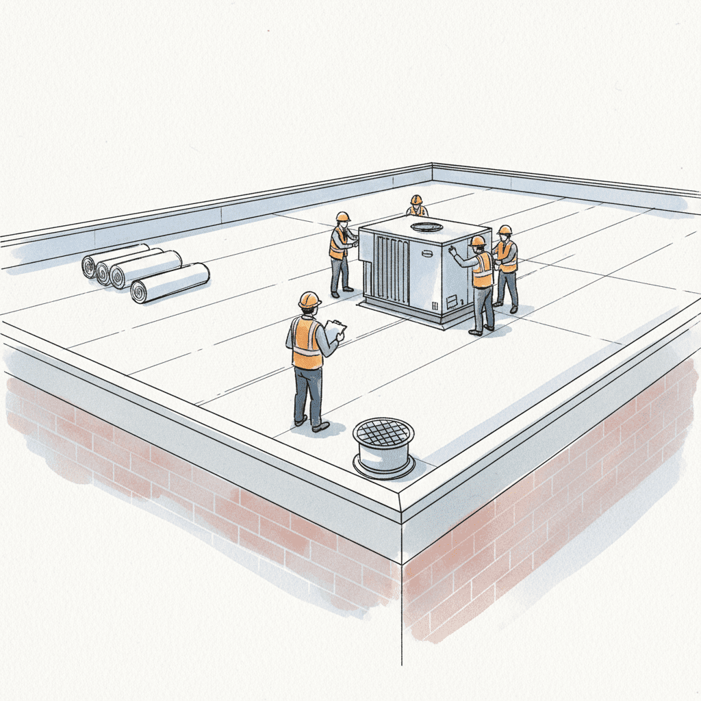
A dedicated project manager oversees all job site logistics. This includes material staging, daily site cleanup, and scheduled progress updates. We manage all inspections and ensure the project concludes with a final quality control audit and system commissioning. There are no surprises.
Why We Reject Projects on Unsuitable Roofs: Our Commitment to Predictability
We decline projects on roofs that do not meet our stringent structural and longevity standards. This is not a sales tactic; it is a core component of our risk management protocol—for you and for us. Installing a state-of-the-art solar array on a compromised foundation invites system failure, voids both roofing and solar warranties, and ultimately destroys the long-term value of your investment. Our refusal to compromise on these initial conditions is our commitment to your financial well-being and our professional reputation. We deliver predictable, high-quality outcomes by controlling every variable. This begins, and ends, with the integrity of your roof.